by ZEVAC
Getting started guide to fleet selection and starting ZEVAC® implementations
INTRODUCTION: What is ZEVAC & How it works
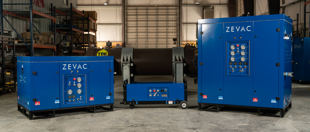
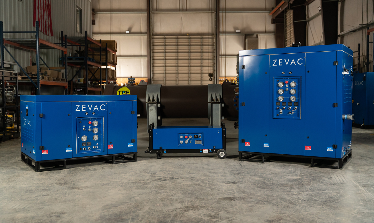
ZEVAC® stands for Zero Emission Vacuum And Compressor. ZEVAC® comes in various form factors and sizes and has been used by natural gas operators and contractors to perform a myriad of tasks. In this application guide, we will explain how ZEVAC® can be utilized to do a wide variety of work without venting gas. These procedures are for informational purposes only and should not be used without good judgment and operational practices. Our goal is to end the practice of intentional venting, and we hope this guide assists you in changing the way you do work for the better.
ZEVAC® works by transferring product (liquids and gasses) from one pressurized system to another. In most applications, this takes the form of moving the product from one part of the system to another by compressing gas from one side (“suction” or “drawdown” side) to the other side (“discharge” or “injection”) of a valve or isolation point. Occasionally, transfers from one system to another separate system are performed, and those differences are noted in this guide.
The ZEVAC® is a linear compressor. This means there is no spinning crankshaft or rotating drivetrain, which affords the ZEVAC® equipment some special functionality and advantages such as handling 100% gas as well as mixed gas and liquids even up to 100% liquid service. Whether your ZEVAC® equipment is pneumatic, hydraulic, or electric driven, you will find the ZEVAC® to be a simple and robust tool that can be integrated into your daily operations with minimal disruption to normal daily operations. The basic working principle is illustrated here:
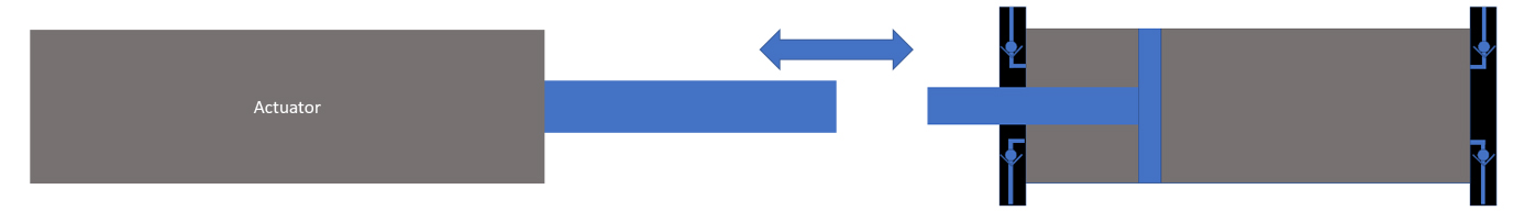
In the ZEVAC® equipment, the actuator is driven in a linear, reciprocating motion. The back-and-forth action of the actuator powers a double-acting compressor section. Together, an actuator and compressor section is called a ZEVAC® Core. Each Core can act independently, and multiple Cores can be arranged in parallel to increase flow rate, or cores can be arranged in series to increase the overall compression ratio and discharge pressure. Each core uses an actuator and compressor section to draw in the product through a set of 1-way check valves to fill the compressor section and then pushes the product out on the reverse stroke through another set of 1-way check valves. In this way, the ZEVAC® core can move 100% liquids, mixed fluids, or 100% gaseous products.
Through this simple and robust, patented functionality, ZEVAC® is used daily to transfer pressurized products in a way that enables operators to depressurize systems for operations and maintenance without releasing the product(s) to the environment.
ZEVAC for DISTRIBUTION SYSTEMS
Natural Gas Local Distribution Companies (LDCs) have unique challenges that are different from other parts of the natural gas supply chain. Some of the issues related to operations and maintenance of LDC systems include:
• Urban Environments
• Traffic
• Odorized Gas
• Public Visibility
• Weather-dependent flow conditions
• Unionized workforce
• Long budget cycles
• Public Utility Commission Approvals
• Overpressure Protection Critical
• Old Infrastructure
• Aggressive ESG Ambitions
This list could go on for several pages, but it is evident through our experiences with LDC operators that what works out in the oilfield doesn’t usually work in the city, and vice versa. We will show in this section how distribution operators are using ZEVAC to perform the following activities without venting gas.
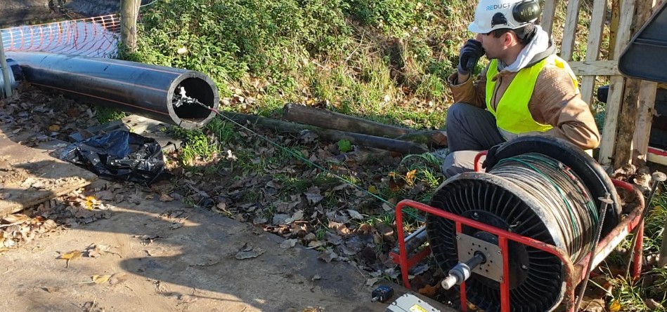
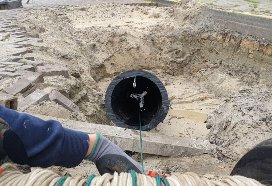
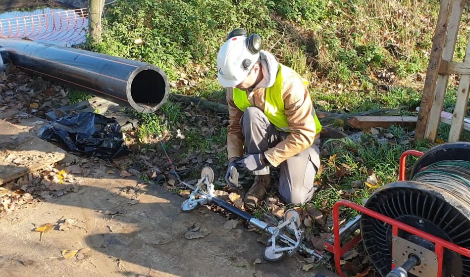
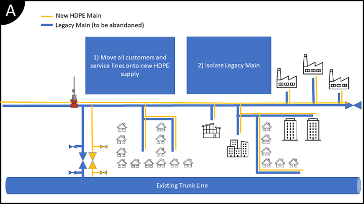
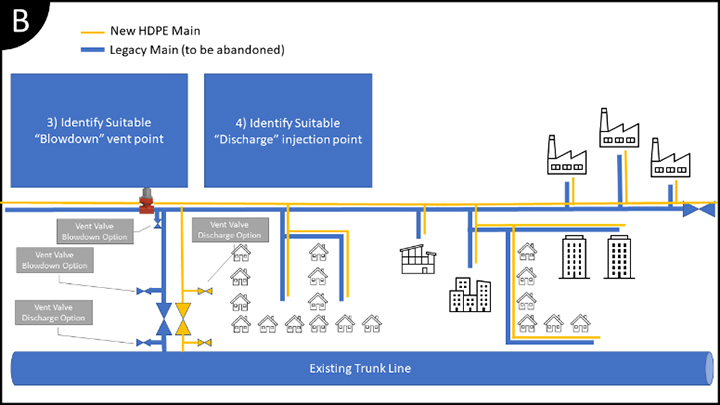
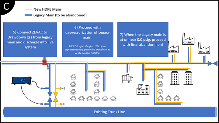
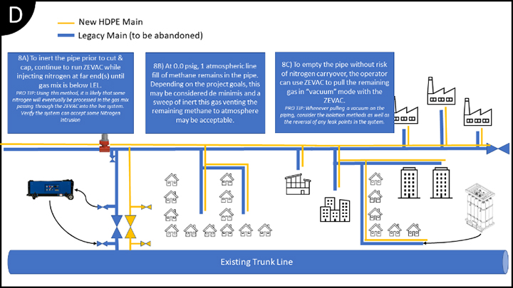
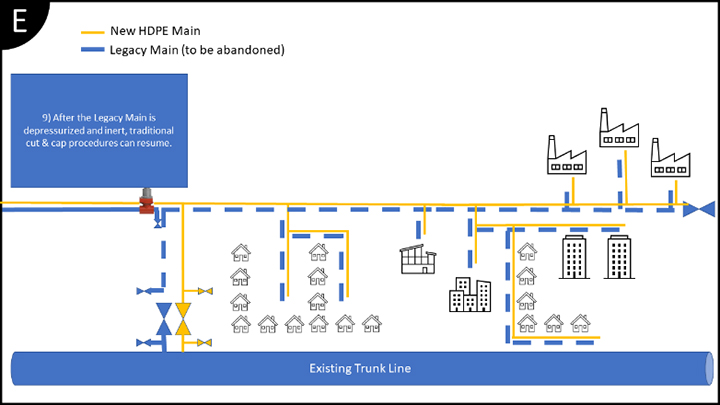
Main Replacements – Main replacement programs are large scale planned operations where old (usually cast iron and bare steel) pipe is replaced with modern piping systems. Traditionally, the old main would be vented for retirement.
Commissioning New Lines – Newly laid distribution piping is traditionally “purged into service” by blowing gas through the lines and venting a gas + air mixture until a suitable gas purity is achieved.
Meters & Regulators – Small systems such as meters and regulators have frequent maintenance requirements such as calibration, repair, and replacement that require the equipment to be depressurized prior to the work being performed.
Odorization – Odorization equipment poses unique challenges related to the saturation of mercaptan that frequently results in “leak” calls if any venting occurs.
Main Repairs – When valve replacements, tie-ins, or cutouts are required, venting is part of the traditional standard procedures.
There are many different approaches to getting started, and we will show 3 ways operators are using ZEVAC® to achieve the same end result, but without the venting of the product. Notes are made in the procedures where we have seen different operators use different methods. Ultimately, each LDC will decide what works best for them, but we encourage operators to challenge their field personnel and contractors to find a way to do the work without venting.
OPTION 1: Maximum Company & Culture Impact
LDC Operators who want to drive ESG goals throughout the company
• Favors higher numbers of smaller equipment placed with many crews
• Impacts as many people as possible
• Drives ESG awareness and “culture of gas containment”
• Equip a high % of people who vent gas to perform capture & recycle
• Address a high % of methane venting occurrences
This approach usually occurs with operators who are currently under or anticipate regulation that focuses on intentional releases. By equipping a large number of people and crews to do daily work without venting, these operators are focused on preparing their workforce to behave in a way that controls the gas instead of releasing. When larger projects occur, these operators can mobilize several of their smaller machines to work in tandem on a large drawdown, mimicking the performance of the larger ZEVAC® equipment.
Sample projects and anticipated results using ZEVAC MINI powered by crew truck air
• 1000’ of 2” pipe, 25 psig → 0 (<5 minutes) [60 scf recovered]
• 5280’ of 8” pipe, 25 psig → 0 (3 hrs) [5mcf recovered]
• 5280’ of 8” pipe, 100 psig → 0 (7 hrs) [14.4mcf recovered]
Sample projects and anticipated results using ZEVAC TWIN LP powered by 185cfm
• 1000’ of 2” pipe, 25 psig → 0 (<5 minutes) [60 scf recovered]
• 5280’ of 8” pipe, 25 psig → 0 (2 hrs) [5mcf recovered]
• 5280’ of 8” pipe, 100 psig → 0 (4 hrs) [14.4mcf recovered]
• 5280’ of 8” pipe, 230 psig → 0 (12 hrs) [30.7mcf recovered]
• 5280’ of 12” pipe, 230 psig → 0 (28 hrs) [69mcf recovered]
• 5280’ of 12” pipe, 400 psig → 0 (48 hrs) [117mcf recovered]
OPTION 2: Large Project Focus
LDC Operators who want to use high-profile projects to deliver emissions reduction
• Favors smaller numbers of larger equipment placed with specialty crews
• Impacts large projects with fewer deployments
• Drives ESG awareness by making high-profile projects emission-less
• Equip a focused group of people who vent gas to perform capture & recycle
• Address a smaller % of methane venting occurrences, typically larger releases per event
This approach usually occurs with operators who are currently looking for a solution to address a handful of applications that have large releases associated with them. By concentrating on a small number of people and crews who are involved with high-emission projects, these operators are focused on getting the “low hanging fruit” in terms of the largest releases. When larger projects aren’t going on, these specialty crews and large equipment can make short work of smaller drawdowns, which can be a good way to show the other departments how quick & easy it is to recover gas instead of venting.
Sample projects and anticipated results using ZEVAC TWIN LP powered by 185cfm
• 1000’ of 2” pipe, 25 psig → 0 (<5 minutes) [60 scf recovered]
• 5280’ of 8” pipe, 25 psig → 0 (2 hrs) [5mcf recovered]
• 5280’ of 8” pipe, 100 psig → 0 (4 hrs) [14.4mcf recovered]
• 5280’ of 8” pipe, 230 psig → 0 (12 hrs) [30.7mcf recovered]
• 5280’ of 12” pipe, 230 psig → 0 (28 hrs) [69mcf recovered]
• 5280’ of 12” pipe, 400 psig → 0 (48 hrs) [117mcf recovered]
Sample projects and anticipated results using ZEVAC QUAD powered by 375cfm
• 1000’ of 2” pipe, 25 psig → 0 (<5 minutes) [60 scf recovered]
• 5280’ of 8” pipe, 25 psig → 0 (1 hrs) [5mcf recovered]
• 5280’ of 8” pipe, 100 psig → 0 (2 hrs) [14.4mcf recovered]
• 5280’ of 8” pipe, 230 psig → 0 (6 hrs) [30.7mcf recovered]
• 5280’ of 12” pipe, 230 psig → 0 (14 hrs) [69mcf recovered]
• 5280’ of 12” pipe, 400 psig → 0 (24 hrs) [117mcf recovered]
OPTION 3: Minimum Company Burden
LDC Operators who want to utilize contractors and non-company resources
• Favors an engineering and standards approach to ESG efforts
• Allows flexibility of scale & timeline vs cost on large projects
• Drives ESG awareness by standardizing emissions reductions into procedures and standards
This approach usually occurs with operators who are organized with an engineering-first structure where a standardized approach is developed and then written into the company’s O&M manual or bid documents. By deploying standards and procedures, these operators enable each department and operating group to scale their efforts up and down as their workloads go up and down. Many LDCs are not doing much venting during the winter due to the slowdown in maintenance activity, and they do lots of work in the summer – so a standards approach allows the operator to avoid being locked into a certain set of equipment and instead places the burden of fleet and manpower onto the crews who are doing that work anyway. These crews, by being on-site already as part of a project, can use ZEVAC in a cost-effective way.
Sample specification language:
“This work has the potential to emit approx. ____ scf of natural gas if performed with a blowdown. All bidders are expected to utilize ZEVAC to reduce actual emissions to <5% of the potential to emit”.
“In support of our sustainability and ESG goals, the company requires the use of ZEVAC or similar emission recovery equipment to reduce all emissions to less than ___ scf”
“Contractor will perform the pipeline cleaning work. During this pipeline cleaning and in-line inspection work, a filter/separator unit with the frac tank will be utilized to separate and collect any debris or liquids that are present in the pipeline. Additionally, on a needed basis, ZEVAC units will be used to recover natural gas eliminating blowdown to the atmosphere. Bidder may provide a separate quote for filter/separator and frac tank, ZEVAC units, and/or combinations of equipment.”
“Contractor is expected to perform this work using tools such as ZEVAC to meet the company’s goal of ____% emission reduction this year. Any work that does not meet this goal should be approved through the project manager for an exception.”
SUMMARY: All of the Above, Eventually
LDC Operators will use all 3 approaches as ESG programs mature
• Large projects will get focus and attention from large equipment and specialty crews
• Smaller, high-frequency work will impact the culture and will align the workforce with ESG
• Contractors respond to standards and bid requirements, which can be modified to transfer the effort to the EPC and contractor workforces who can act as a peak-shaving and force-multiplying lever for LDC operators to use.
For more information on the ZEVAC and to request a demonstration, click here.
About ZEVAC
ZEVAC was founded in 2014 as TPE Midstream and holds multiple issued and pending patents on the ZEVAC and its underlying technology. ZEVAC also operates a full-service equipment rental division, with offices in Pittsburgh PA, Tulsa OK, and Temecula CA. ZEVAC supports operators by providing the equipment they need to perform pipeline system maintenance safely while being heroes in their neighborhoods and taking care of the environment they operate in.